


Language 


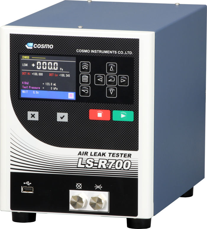
New generation: DP air leak tester High-performance standard type
LS-R700

Edge & Function
Main menus are classified by icon
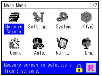
The menu screen is easily displayed with an icon.
You can understand in an instant the display of the program lock state and [M] manual/[R] remote.
The language can be easily switched from here.
Can switch between 3 kinds of measurement screen
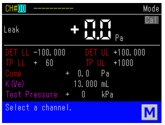
The above measurement screen is a detail screen.
Each set value and necessary information can be viewed.
The measured leak volume is simply displayed with the standard screen, and a waveform display screen is also available.
The display method can be switched according to the situation.
Each type of settings screen
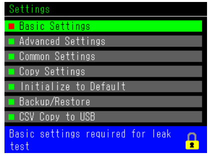
Menu screen for configuring settings related to leak test.
Choose the required items, configure and copy, and the USB port can be used to download the settings value file.
Explanation displayed on guidance bar
The blue bar beneath the screen is the guidance bar.
The help text for the selected part is displayed in the guidance bar.
Therefore it is possible to operate smoothly even without a user manual.
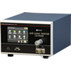
Compact body allows for setting up in a variety of places.

Vertical compact body with dimensions W195 x H250.2 x D304.7.
Despite its small size, all functions for running leak tests such as the intelligent pneumatic circuit are included.
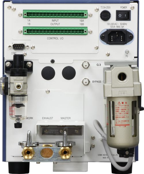
Phoenix Contact product is used for input/output connector

Phoenix Contact product was adopted for the controller I/O connector of the input/output interface.
The connector is very reliable, and the wiring work can be done with a flat-head screwdriver, so that the work efficiency increases.
Function for switching between the 3 main national languages
Supports Japanese, English, and Chinese.
Overseas expansion is simple.
Easy data collection with USB port
Measurement data is automatically saved to USB memory.
Other settings information can also be backed up with USB memory.
Performance improvement function
Safety/Reliability improvement function
Pneumatic Circuit
Spec
| Differential pressure | Resolving power Precision guaranteed range Excess pressure on sensors Sensor precision |
0.1 Pa ±1000 Pa 5 MPa ±2.5% of rdg ±1Pa, however 50Pa or below is ±2Pa |
|---|---|---|
| Display units | Test Pressure: | kPa、MPa (Non-SI units for overseas: PSI, kg/cm2, bar, mbar, mmHg, cmHg, inHg, etc.) |
| Leak volume | mL/min, L/min, mL/s, Pa/s, Pa/min, Pa, kPa, Pa・m3/s, E-3 Pa・m3/s , etc.(Non-SI units for overseas: mmH20, mmHg, inH20, etc.) | |
| Displayed leak volume | 4 digits, sample rate: 10/second | |
| Number of Channels | 32ch(0~31) | |
| Timer setting range | 999.9 seconds (resolving power: 0.1 second) | |
| Power Source | AC100~240V±10%, 50/60Hz, 70VAmax | |
| Test pressure source | Uses clean air. The original pressure must be sufficiently higher than the test pressure. |
|
| Pilot pressure source | Applies 400 to 700kPa of clean air. | |
| CPU | SH-2A 144MHz, DRAM 8MB | |
| Pipe connection diameter | Rc1/4 (test pressure supply, workpiece piping, master piping) 6mm one-touch joint (pilot air supply) |
|
| Ambient temperature | Operating temperature 5 to 45°C Storage temperature: -20 to 60°C | |
| Humidity | 80 %RH or less No dew condensation | |
| Mass | Approx. 10kg | |
| Serial communications RS232C-based (D-sub9-pin) |
I/F fixed length output | Leak data and set values are outputted simultaneously |
| ID/F fixed length output Standard settings |
Leak data and set values are outputted simultaneously | |
| T/F fixed length output | Only leak data outputted | |
| USB Port | Saving data | Saves decisions, leak values, test pressure, WK#, CH#, and time on inserted memory. |
| Set value output | Set values of all settings screens | |
| Standard accessories | Power cord | For use in Japan: Rating: AC125V/7A, length: 3m
For export: Rating: AC240V/10A, length: 2m (CE conformant product) |
| Control I/O connector, cap for RS-232C, USB cover, test report, traceability documents, user manual | ||
Classification
■ Model LS-R700 – A B Options
| A | Measurement Circuit | Intelligent 1 Pneumatic Circuit | A1 | Large air flow rate, and sensor protecting circuits are included. | ||||||
|---|---|---|---|---|---|---|---|---|---|---|
| Intelligent 2 Pneumatic Circuit | A2 | Uses two-way delivery valve, reliability is ensured and self-check functions are fully available. | ||||||||
| Circuit for micro volumes | AS01 | For target workpieces 10mL or less (standard) with standard leak values that are particularly small | ||||||||
| A1 circuit for small volumes | AS1 | Used for workpiece volumes 100mL or less, when high detection capability is required.。 | ||||||||
| External pressure detection circuit | C | External pressure detection type (secondary pressure method) | ||||||||
| B | Test pressure range and control pressure specifications | Precision regulator specifications | For micro pressures | L02 | Operating range: 5 to 20kPA (PS 20kPa, pressure control valve: 200kPa) | |||||
| For low pressure | L | Operating range: 10 to 100kPA (PS 100kPa, pressure control valve: 200kPa) | ||||||||
| For medium pressure | M | Operating range: 50 to 800kPA (PS 1MPa, pressure control valve: 0.8MPa) | ||||||||
| For high pressure | H20 | Operating range: 2.0MPa or less (PS 2MPa, no pressure control valve) | ||||||||
| For vacuum | V | Operating range: -5 to 100kPA (PS -100kPa) | ||||||||
| Electro-pneumatic regulator specifications | For low pressure | LR | Operating range: 10 to 95kPA (PS 100kPa, pressure control valve: 100kPa) | |||||||
| For medium pressure | MR | Operating range: 50 to 800kPA (PS 1MPa, pressure control valve: 0.9MPa) | ||||||||
| For vacuum | VR | Operating range: -5 to -75kPA (PS -100kPa, pressure control valve: -80kPa) | ||||||||
| O p t i o n s |
Leak Master support | J | Leak MasterBuilt-in control valve | During K (Ve) calibration and K (Ve) check, the calibration port automatically opens and closes. Not suitable for high pressure.
Leak Master is sold separately. |
||||||
| Bypass support/reducing valve not included | B | The valve that controls the bypass unit is built in. Bypass Unit is sold separately. |
||||||||
| Checks if manual valve was not open | W | Prevents running of test while stop valve is closed. | ||||||||
| Nylon filter case | RX02 | The filter case of the pilot pressure connection is made of nylon. | ||||||||
| RX03 | The filter case of the test pressure and pilot pressure connection is made of nylon. | |||||||||
| Wide range DP display | D4 | DP sensor range ±10kPa resolving power (minimum display): 1Pa | ||||||||
Appearance

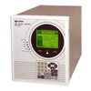
AIR LEAK TESTERS
Air Leak Tester is the automatic leak detector detects any leaks by the minute change of differential pressure and conducts OK/NG judgment.
Ideal to be built into a production line for a laborsaving and a quality control purpose
AIR LEAK TESTERS
HELIUM/HYDROGEN LEAK TEST
Helium Leak Tester adopts the new testing method and Helium Leak Tester adopts the new testing method and
HELIUM/HYDROGEN LEAK TEST
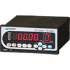
PRESSURE
All Manometer comes with a traceability. Wide range of Manometers, from a micro pressure (F.S. 200Pa) to a high pressure (F.S. 50MPa) are available
PRESSURE
FLOW
Variety ranges from F.S.10mL/min to F.S 500L/min are available.
Promotes an automation and a laborsaving of the measurement
FLOW
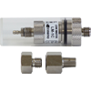
PERIPHERALS
Peripheral instruments are used with Air Leak Tester in order to enhance its functionality and convenience
PERIPHERALS